One of the most popular questions that is being frequently asked in many Embedded Software Interviews is How to Generate a PWM Signal using Clear Timer on Compare (CTC) Mode.
In this article we are going to to answer this question step by step with the help of simulation to understand how to approach these kind of questions in an interview. The demonstration of this problem answer is for the ATmega32A micro-controller.
Software needed:
-
Atmel Studio 7

-
Proteus 8

Problem Statement:
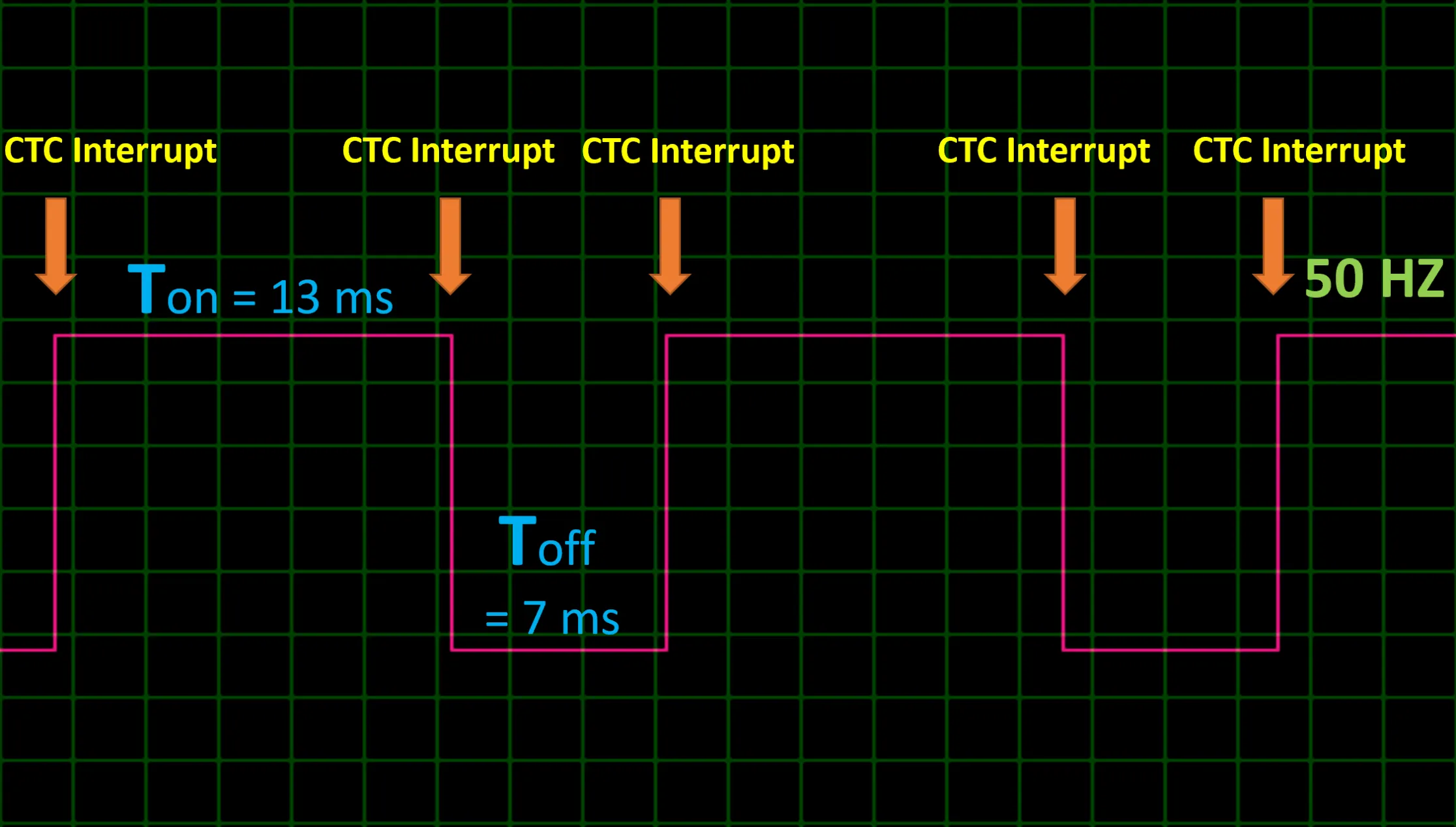
Let us assume that we need to generate a 50 Hz PWM signal having 65% duty cycle.
Analysis:
Given that the frequency of our signal is 50 Hz. We can calculate the time period of this signal using the below equation:

So, The Time Period , T = T(on) + T(off) = 1/50 = 0.02 s = 20 ms
Also, given that the Duty Cycle of the signal = 65%. With help of the duty cycle equation below, we can find the time period, Ton, and Toff.

- Ton = 13 ms
- Toff = 7 ms
Now that we have these valuable information, we can start developing a solution for our problem.
The key to our solution is the Timer Interrupt of the CTC mode of the timer; we know that to generate this PWM signal we need to set a certain pin High for a 13 ms period of time, and then set its value to Low for a 7 ms period of time. We are going to use Timer1 in the Atmega32A Micro-controller to generate these time periods.
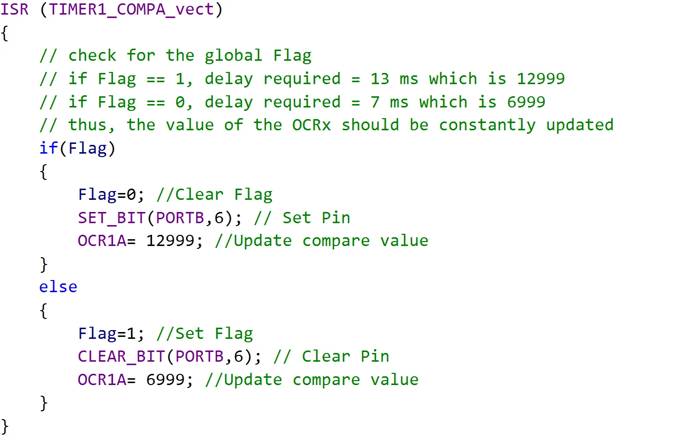
We can do that by adjusting the compare value of the timer inside the Interrupt Service Routine(ISR) that is fired when a compare match happens. This is done by checking the value of a global Flag; we assume that if the Flag value is 1, then we set the pin and update Compare value of the OCR register. And, if the value of the global Flag is 0, we clear the pin and update the OCR register with the Toff compare value.

After we knew how are we going to approach this question, let us see how to calculate the Timer Compare Value required to generate the Ton and Toff time periods.

After using the above equation we can easily calculate the timer count that is required to generate the Ton and Toff periods. Assuming that the frequency of the micro-controller is 1 MHz we can get the below count values for each time period.


Now that we have the compare values required to generate these time periods, let us implement the ISR code that is going to develop our desired signal as we mentioned above.
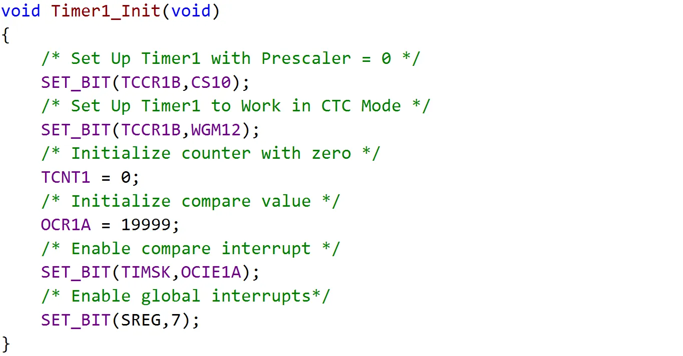
After we implemented our logic to generate the PWM signal inside the ISR code, let us implement a function that sets up Timer1 to work in CTC mode and fires an interrupt on compare match.
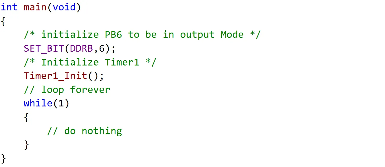
Now that we implemented our function to initialize Timer1, we need to set up a certain pin to work in output mode to be able to generate the PWM signal; this is done in the program main function, and we also call the Timer initialization function in our main function.
After implementing all necessary parts needed to generate this PWM signal, it’s time to upload our code to the micro-controller and see the results.
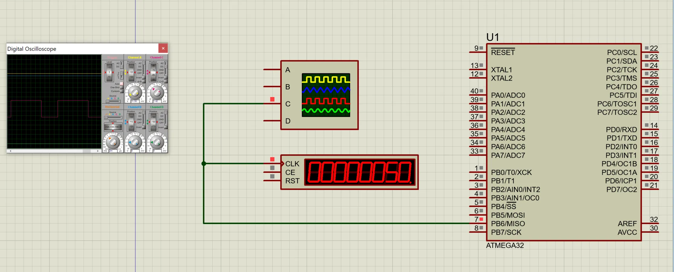
As you can see we managed to Generate the required PWM Signal with a 50 Hz frequency using CTC mode of Timer1.
You can find the source code and simulation through this link: GitHub - AbdelazizMoustafa10m/Generate-PWM-using-CTC-mode