Unit Testing
In some situations, the goal of the developer is to test a single feature of the software, purposefully ignoring the other units of the systems. When we test units in isolation, we are doing what is called unit testing.
Defining a ‘unit’ is challenging and highly dependent on the context. A unit can be just one method or can consist of multiple classes. Here is a definition for unit testing by Roy Osherove:

Unity
Unity is a unit testing framework for C (ESPECIALLY EMBEDDED SOFTWARE). Its goal has been to keep it small and functional. The core Unity test framework is a single C and a couple of header files, which provide functions and macros to make testing easier.

Most of the framework is a variety of assertions that are meant to be placed in tests to verify that variables and return values contain the information that you believe they should.
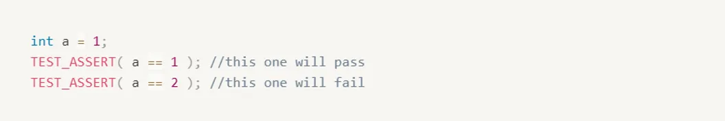
Unity is most obviously about assertions. Assertions are statements of what we expect to be true about our embedded system. At their most basic, they are things like this:
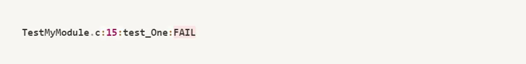
You could use nothing but the TEST_ASSERT above, and you could test almost anything that your C code can handle… but when something went wrong, you’d see something like this:
Creating A Test File
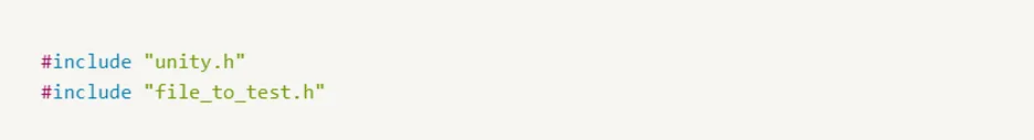
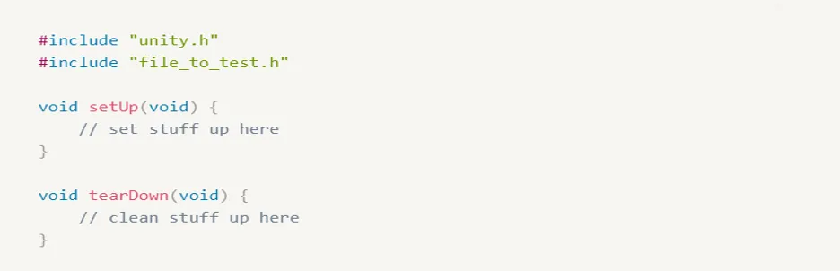
Test files are C files. Most often you will create a single test file for each C module that you want to test. The test file should include unity.h and the header for your C module to be tested.
Next, a test file will include a setUp() and tearDown() function. The setUp function can contain anything you would like to run before each test. The tearDown function can contain anything you would like to run after each test. Both functions accept no arguments and return nothing. You may leave either or both of these blank if you have no need for them.
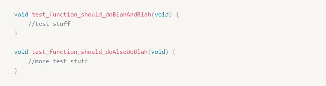
The majority of the file will be a series of test functions. Test functions follow the convention of starting with the word “test” or “spec”.
You don’t HAVE to name them this way, but it makes it clear what functions are tests for other developers. Also, the automated scripts that come with Unity will default to looking for test functions to be prefixed this way.
Test functions take no arguments and return nothing. All test accounting is handled internally in Unity.
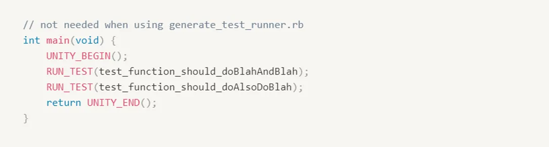
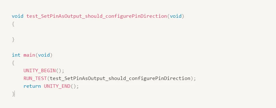
Finally, at the bottom of your test file, you will write a main() function.
This function will call UNITY_BEGIN(), then RUN_TEST for each test, and finally UNITY_END().
This is what will actually trigger each of those test functions to run, so it is important that each function gets its own RUN_TEST call.
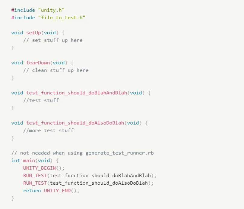
When you’re done, your test file will look something like this:
Running Test Functions
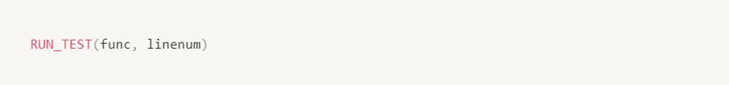
When writing your own main() functions, for a test-runner. There are two ways to execute the test.
The classic variant:
Or its simpler replacement that starts at the beginning of the function.
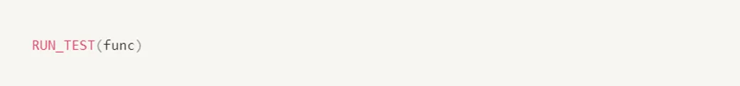
These macros perform the necessary setup before the test is called and handle cleanup and result tabulation afterward.
Build System Setup
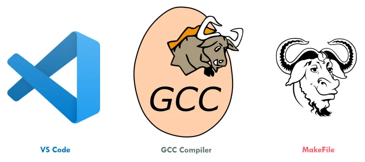
In order to start testing your embedded code, you can use VS Code as a text editor, GCC compiler installed on your machine, and a simple makefile to automate your build.
How to Unit Test?
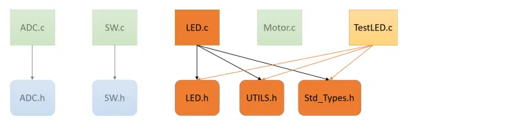
Let’s say that your software is composed of the below modules and you want to test the LED module.
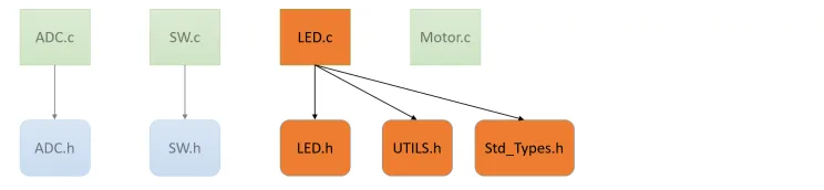
You need to create a test file for the LED module and it should include all the files needed by LED.c
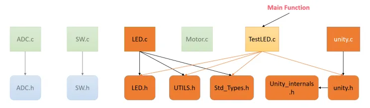
Then, you need to add the core files of unity to start testing your LED module and the test file should include unity.h file also.
Suggested Directory Layout
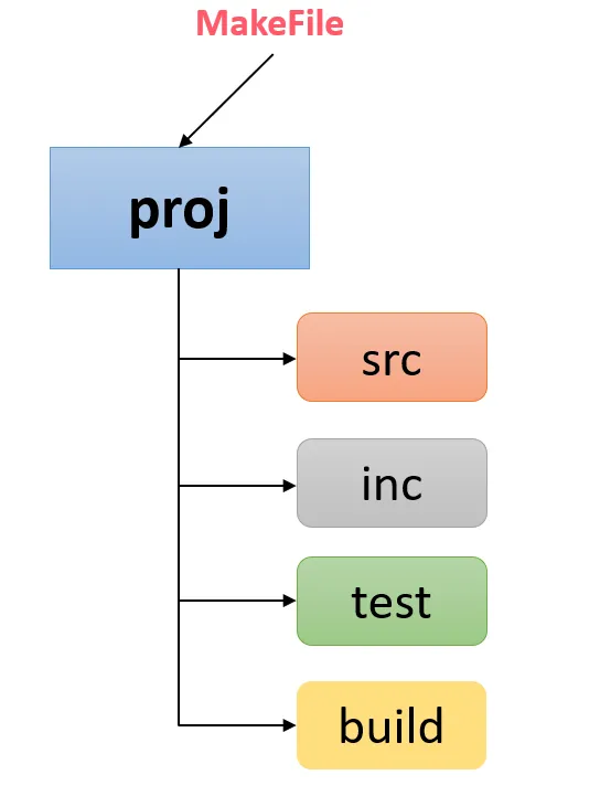
In the spirit of keeping your release source separate from your Tests, we recommend structuring your projects so that the source code and the tests are in separate folders.
This organization makes it easier to tell your code apart and to find what you’re looking for.
It also simplifies the automation of both test builds and release build the details of those depend on your needs of course
Our First Test Case
GPIO Unit Test, We will learn how to create source and tests together and how we work with registers. we can start with a small module we can develop. will create this interface for a Freescale Kinetis K20 ARM Cortex-M4; and if you are not familiar with this target, don’t worry that’s the whole point that we are able to unit test our code independently from the hardware itself.
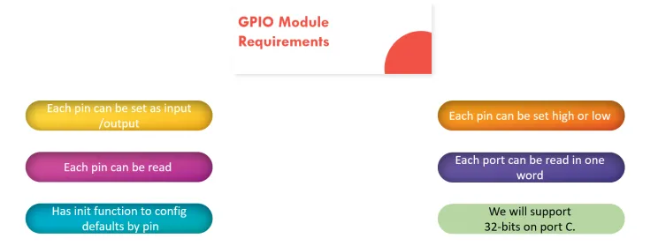
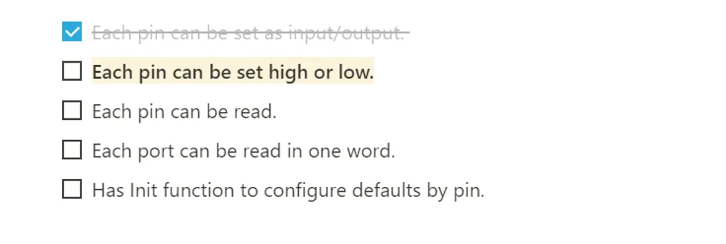
We can start from our first requirement which is Each pin can be set as input/output
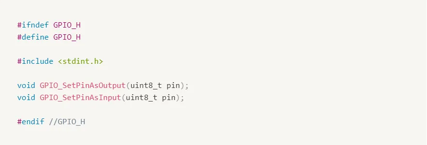
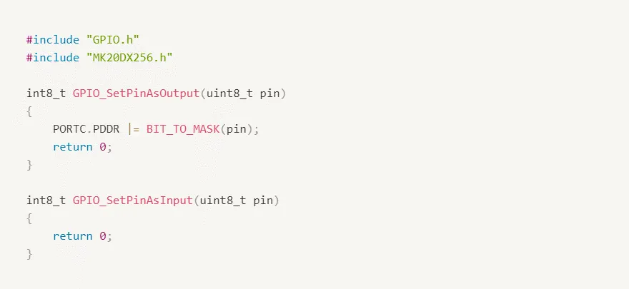
If you open the GPO header file, the very first thing we want is to add a function declaration for our new function. Maybe they look something like this.
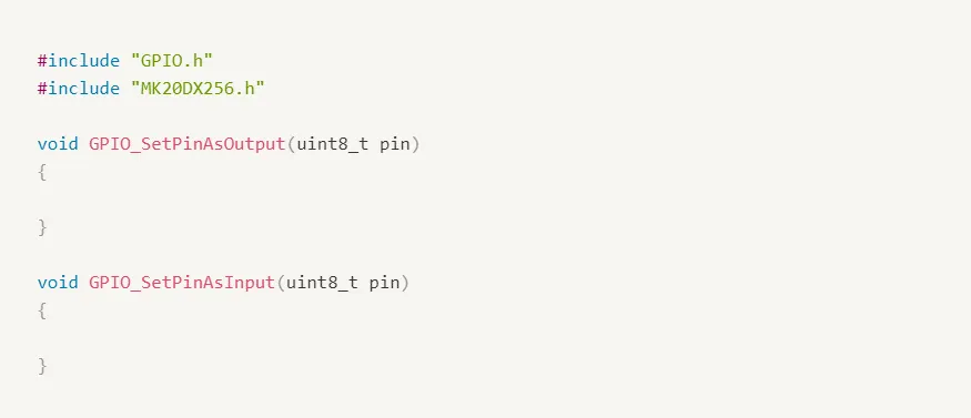
Next open GPIO.c; We’re not going to do much here just add an empty declaration for each of the functions we just declared.
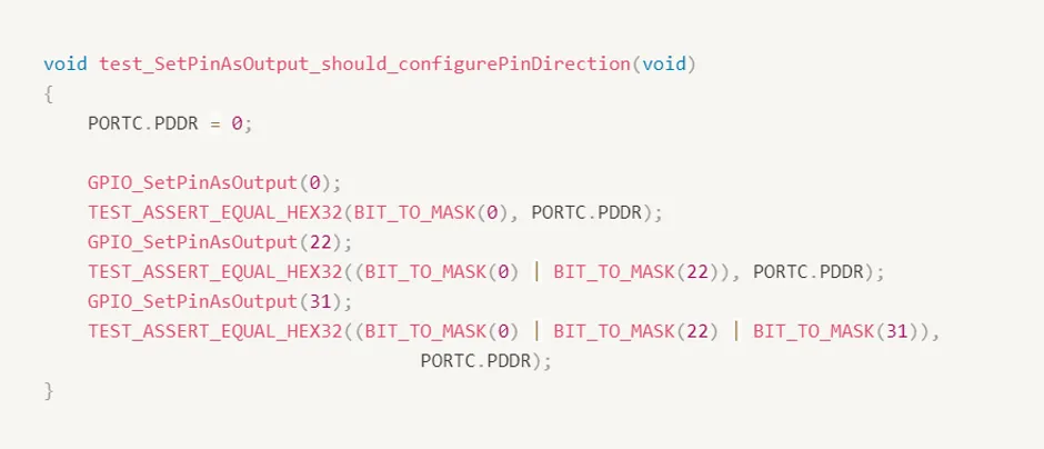
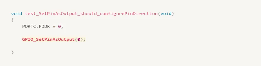
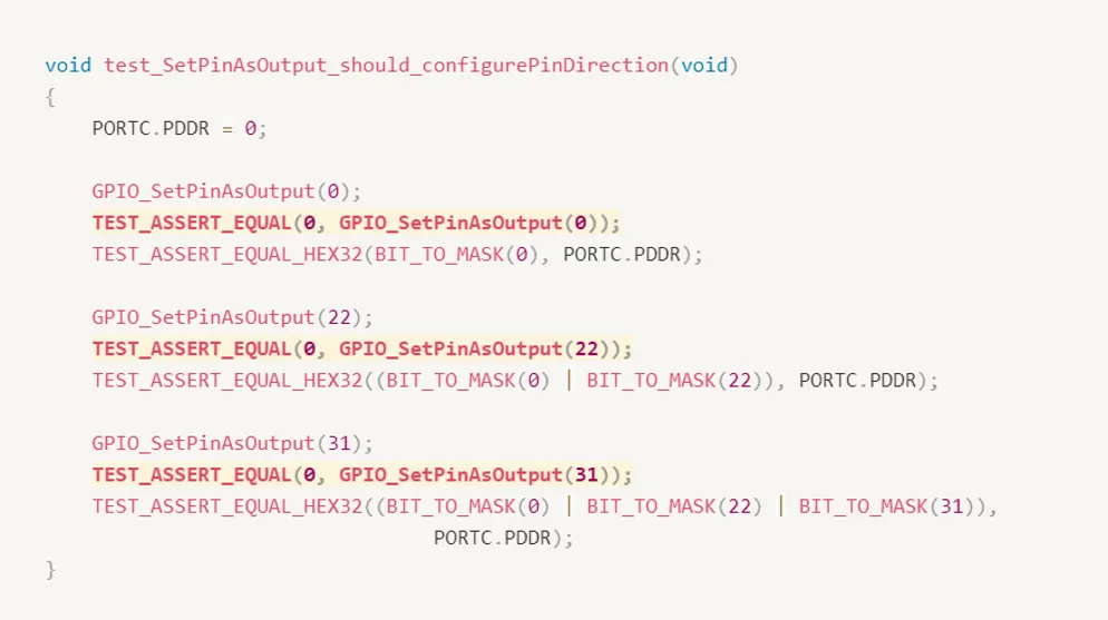
We start by writing tests for our first requirement that we could configure pins as inputs or outputs. We name our test to something appropriate like set pin as output should configure pin direction. The first part is the name of the function we’re writing a test for the second part of the test name is what we expect that the function under test should be able to do.
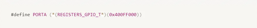
Before writing our first test, we should have a look inside our Microprocessor registers definition file. First, you see that there’s a typedef of a struct covering all the control registers for a port.
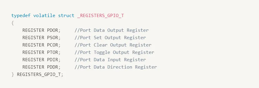
when compiled in their final release, this typedef is used to virtually layout the C struct over the specific hardware memory address for this Micro’s definitions.
But yes I can hear you say that I am writing and executing these tests on my PC, not the real MCU; so let’s find out how to test registers.
How to Test Registers
This is one of the classic questions about unit testing embedded code: How do you test registers? Ideally, you’re not running real hardware here (that’s for system tests). You are most likely running either a simulator (getting to use your real compiler) or using a native compiler to compile native test apps (probably faster).
Let’s say the testing is a native executable on your development machine instead. You can’t exactly just write to any memory location you want and assume it’s going to be ok (address 0x1234 might be the LED port on your micro, but I bet it’s not on your development PC!).
Your goal is to position registers somewhere where it is safe to write and read. You don’t want to have to change much of your main code, though, so it’s all about how the registers get defined.
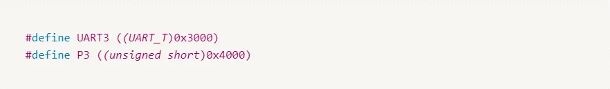
First, look at the micro’s register definition file. Sometimes it’s a bunch of structs placed in certain locations… sometimes a bunch of defines.
We’re going to copy this file and make one that is used only for tests. When you build your release, you’ll still use the original, but tests will use this new one. It’ll be work, but it’s going to make testing so much easier!
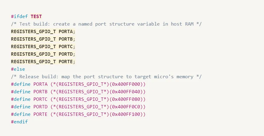
For those registers defined in structs, just remove the location-specific part of the definition so that the linker will just create it somewhere.
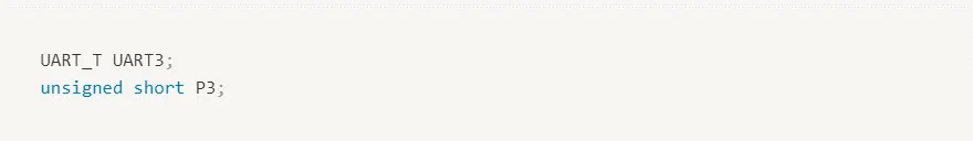
When you’re dealing with a pointer de-reference define, replace it with an actual variable… it’ll then get mapped somewhere safe by the linker.
So our test version will look like the following:
Another option is to modify the Micro’s registers definition file. During a test, our micro definition file now creates support structures for us in RAM and it does not map them to hardware addresses. Our build will define the preprocessor symbol TEST during our test build.
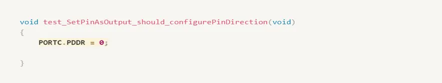
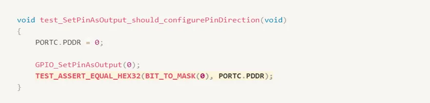
Back to our test file, we were working with configuring output and input direction for Port C so we know that we’re going to need port data or direction register.
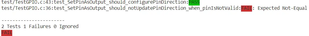
After running make test command, we can find that our test failed.

The first step of our unit test is a failing test, now It’s time to update our source and make it pass.
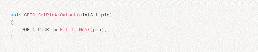
Remember we are trying to write the minimum amount of code to make our test pass so resist the urge for writing any fancy boundary checking for now.
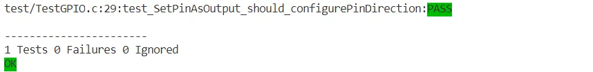
Running our test again, we can find that our test passes.
Unit Test Pattern
Set up starting conditions
Run function under test with known arguments
Verify effect
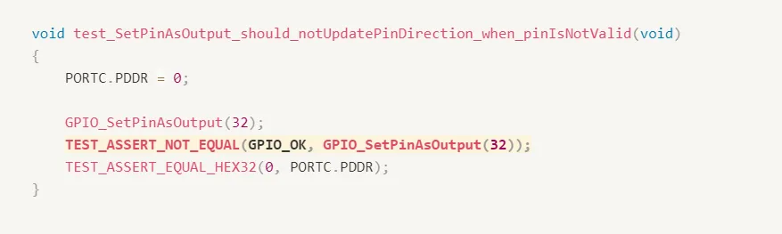
So does our first test perform a sufficient verification that our function is working as intended? Well, it does a nice job of showing how it should work- Our Happy Day Test -What about those boundary conditions. We were just talking about what happens if we ask for 32. That seems a good time to write our second test
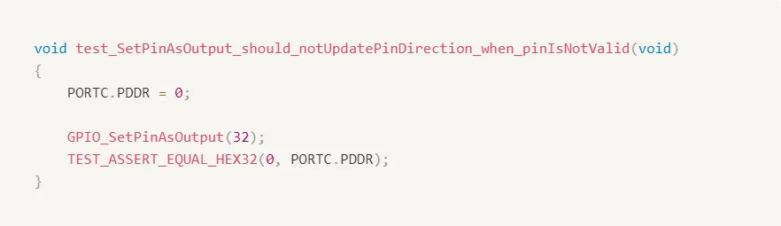
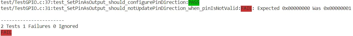
Running our test again, we can find that our second test fails as expected.
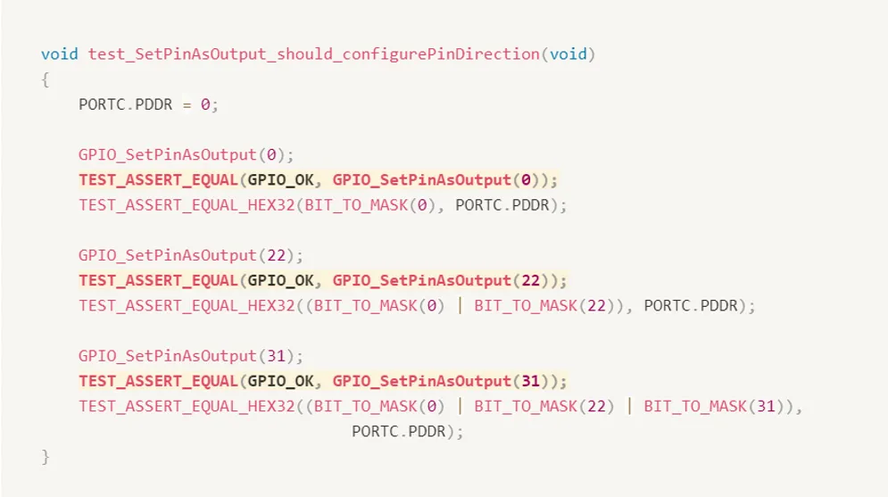
So, let’s modify our source and our test to handle a return value. We’re going to go with the standard of returning zero when everything is going well and returning something else when there’s a problem. So we need to update our source file and our header file first. We’ll start by returning zero all the time to get us going.
We need to update our tests to check our return values
A very good idea would be to add definition to our return codes and our GPIO header file
In our second test, we’re going to use TEST_ASSERT_NOT_EQUAL because we know that the situation should return some sort of error condition if we want to check for a specific error code. We could use our normal equal comparison and put the value here. But right now we only care that it isn’t equal to zero.
Running our test again, we can find that our second test fails as expected.
Our second test now knows that even though we’re giving an illegal value it’s treating it as if everything were fine. So now we should fix this.
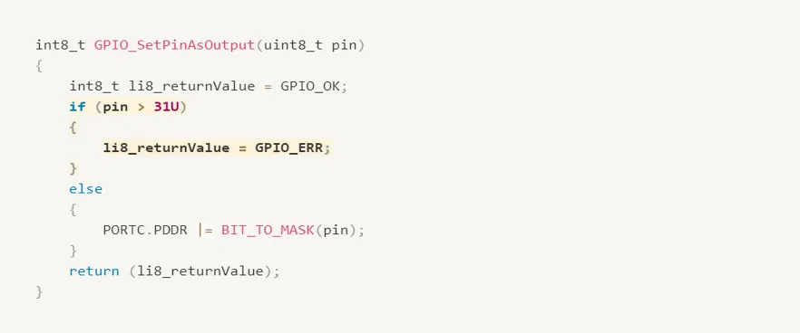
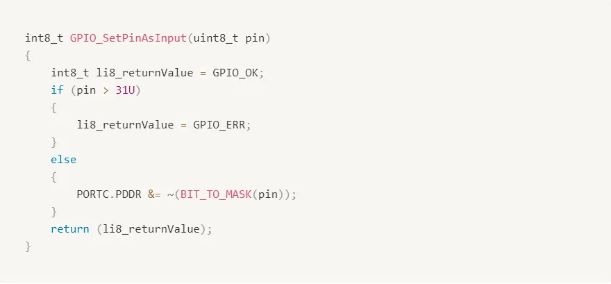
There are a few ways to approach this problem. Probably the cleanest method is to use a simple IF statement. We just check to see if our value is too big and return a non-zero value if it is otherwise, we proceed
Now it’s time to move on to our input’s function.
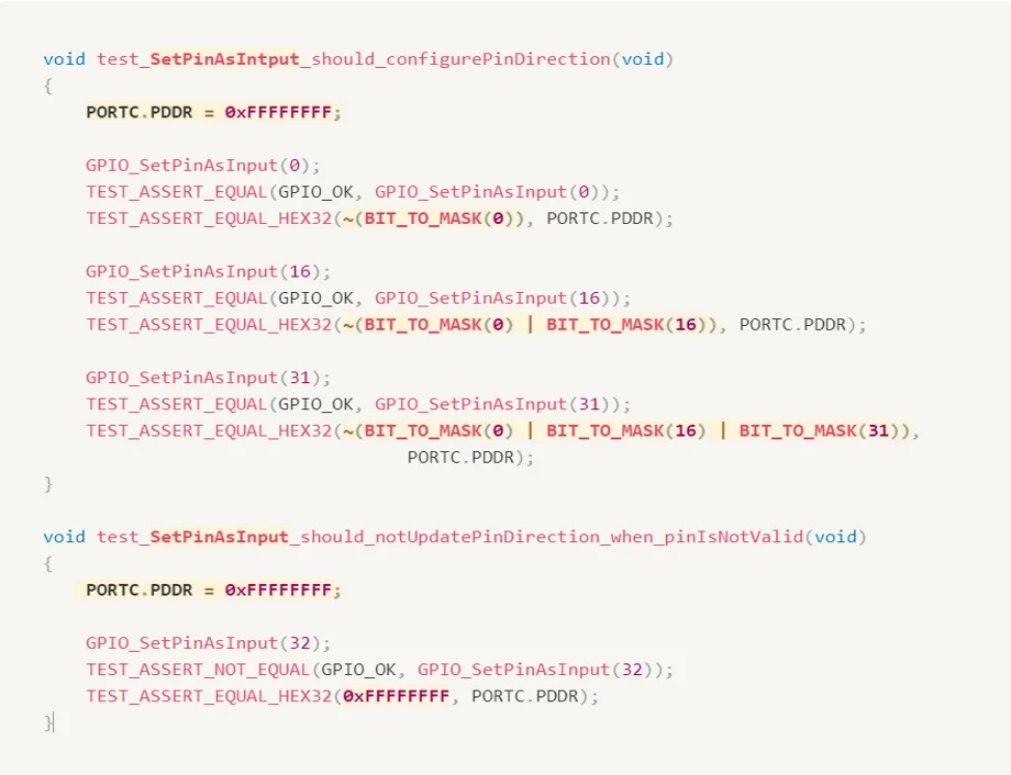
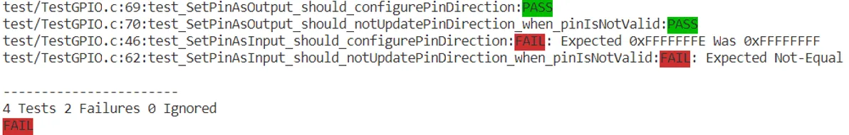
Of course, since we haven’t implemented this new function both new tests fail the first complaints about the bitmask looking incorrect. The second complains about a return code being 0 when it should not have been.
So, we switch to our source file and we implement the input function to make the tests pass.
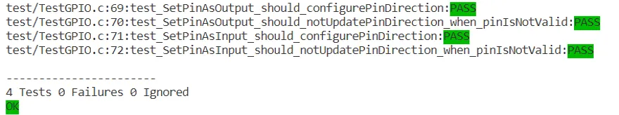
Running our test again, we can find that our two tests for the input function pass.
The Flow
Writing a Failing Test
Each time we wanted to work on a feature we started by writing a test. This test was the next detail of how our module should work but didn’t yet actually work that way. This test therefore failed.
Make it Pass
We then wrote the minimal amount of code to make that test pass and keep any previous tests passing as well.
Refactor
Once it was passing, we then had the ability to refactor our source to follow good coding practices.
Repeat
When we were happy with our refactoring we started over again with the next test.
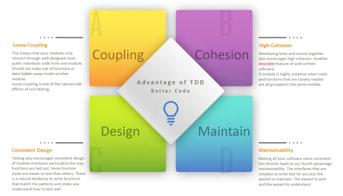
As you may have guessed there is a name for this flow. It’s called test-driven development or TDD.
Test-Driven Development (TDD)
Test-Driven Development is a technique for building software incrementally. Simply put, no production code is written without first writing a failing unit test.
Test-driving is logical. Instead of diving into the production code, leaving testing for later, the TDD practitioner expresses the desired behavior of the code in a test. The test fails. Only then do they write the code, making the test pass.
TDD Vs. DLP
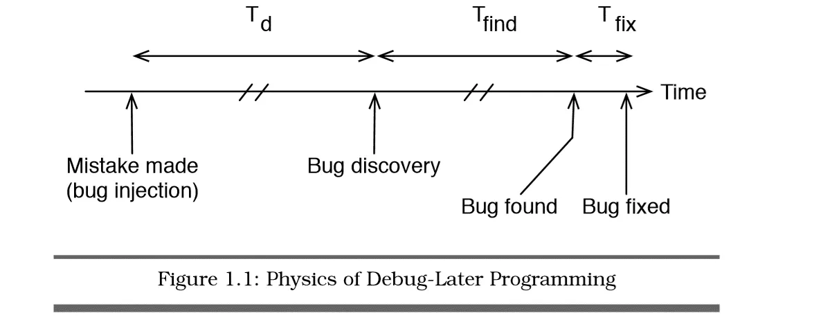
In DLP, code is designed and written; when the code is “done,” it is tested. Interestingly, that definition of done fails to include about half the software development effort.
It’s natural to make mistakes during design and coding - we’re only human. Therein lies the problem with Debug-Later Programming; the feedback revealing those mistakes may take days, weeks, or months to get back to you, the developer.
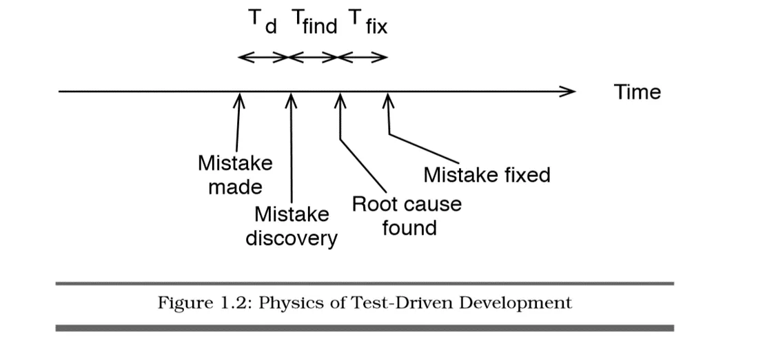
TDD makes you decide what you want before you build it. It provides feedback that everything is working to your current expectations.
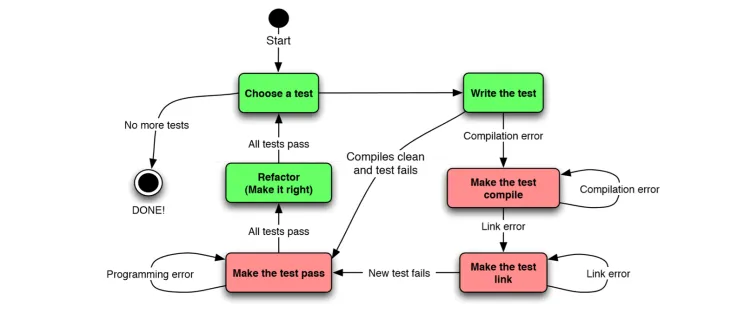
At the core of TDD is a repeating cycle of small steps known as the TDD microcycle. Each pass through the cycle provides feedback answering the question, does the new and old code behave as expected? The feedback feels good. Progress is concrete. Progress is measurable. Mistakes are obvious
TDD State Machine
Behavior Driven Development (BDD)
Specialization of TDD
BDD is a formalized evolution of TDD that encourages specifications - that’s their name for tests - to be written before code and according to a standardized format. Most of BDD is standardization of verbiage though it also encourages tests for a unit of code to be the focus.
User Stories
BDD focuses on the use of user stories. Sentences of text in a specified format help the developer to think about how they want a unit to behave through a standardized format. The actual format of these user stories changes from team to team but it’s encouraged that a team adopt one that works for them and sticks with it.
Let’s look at a couple of popular formats really quickly.
User Stories
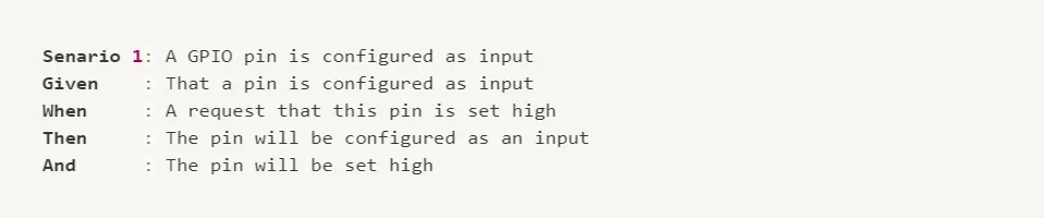
One option is the original BDD user story format developed by Dan Norris. It starts with an opening scenario to be covered by the spec. It then states starting conditions as Given’s and states what should happen to change things with a when statement. Finally, it says what we should then see. In spirit it’s similar to our simple test pattern, isn’t it?
The second format is sometimes called the spec format. It’s creating a specification for how we expect a module to act. It describes a module at a time then speaks of what it should do over various situations. Each should statement basically equates to an assertion there are many good test frameworks out there that support this framework natively.
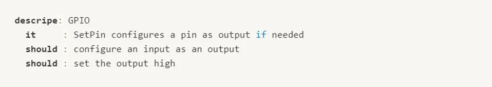
The user story we’ve adopted for this series is contained in this single line spec that is also a test function name though everything is squished into a single line. It still provides a clear and consistent way of describing what we want to happen.
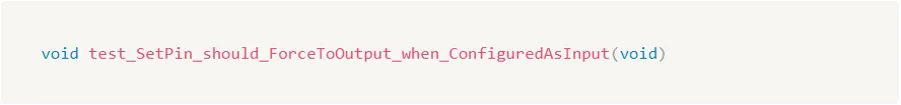
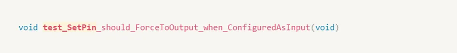
It starts with a test because our spec is a test. And this convention will support later aspects of automation. The spec then immediately identifies the source function we’re testing
Then followed by what we expect this source function should do.

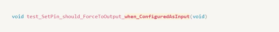
Finally, when we expected to accomplish the result of the tested behavior.
Looking at our list of features we finished testing the first requirement. Now you can continue with the same steps to test all remaining features.
References
- Unit Testing & Other Embedded Software Catalysts | Udemy
- Embedded Testing with Unity and CMock
- Test-Driven Development for Embedded C | James W. Grenning
- Unity Website